3DEXPERIENCE Customization Guide
3DEXPERIENCE Platform provides diverse options for openness, configuration and customization. In this article we discuss the various options.
Introduction
3DEXPERIENCE Platform comprises various applications and services. It also has platform administration control centres to Manage members, role-based access, usage analytics and application behaviour configuration.
3DEXPERIENCE Platform Customization Guide details out the customization practices for doing enterprise-grade 3DEXPERIENCE platform Customization. It also details the various customization capabilities available on the platform.
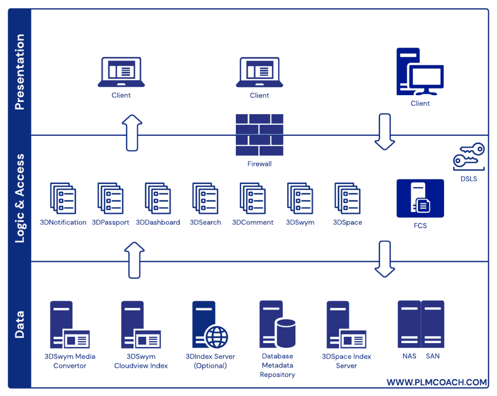
3DEXPERIENCE Platform Architecture
3DEXPERIENCE Platform Architecture comprises 3 layers. The data, logical and presentation layers respectively
Get Trained on 3DEXPERIENCE from PLM Coach
Baseline vs CSE
Below Table summarizes the differences between Baseline and Customer Specific Environment
| Features | Baseline Environment | Customer Specific Environment (CSE) |
|---|---|---|
| Scope | Applicable to both On-premises and Cloud platforms. Comes with a pre-defined, ready-to-use, limited customization capabilities. Allows configuration (not as deep as for CSE) directly from the web-based user interface. | Only applicable for On-premises platforms. Involves configuration and customization from scratch. |
| Collaborative Space | In 3DSpace Baseline Environment we have only flat structure of defined (Public, Protected, Private, Standard) Collaborative Spaces. | A hierarchical structure can be achieved only in a Customer-Specific Environment. |
| Role | There are predefined Horizontal roles Applicative roles (Public reader, Reader, Contributor, Author, Leader) Administrative roles (Owner, administrator) Restricted roles (Reader, Contributor, Author, Leader, Owner) | Vertical roles are associated to the Host Company and the Collaborative Spaces to display the contexts in the web interface. 3DSpace Native Apps do not have Vertical Roles |
| Organization | Hierarchical structure of organizations is allowed | Hierarchical structure of organizations is allowed |
Please note the following important points regarding Baseline Environment and Customer Specific Environment (CSE):
- The decision to go with horizontal roles (3DSpace Baseline Behavior) or with vertical roles (CSE) depends on the level of access granularity which is required.
- Roles will be a key factor to decide between 3DSpace Baseline Environment or CSE for a customer.
- Administrative users can choose to configure the Baseline behavior or Customer-Specific Environment (CSE) solution.
- Although it is possible to switch between solutions later on, the choice should not be modified after initial configuration. Each solution creates objects specific to that solution, and they are incompatible with each other.
- After users start using one of these environments, changing to the other is not supported (even though the tools may allow it)
- Upgrade of configuration/customization made to the platform while following the Baseline Behavior is supported by Dassault Systèmes R&D. Customizations made through MQL and Spinner utility in CSE mode are not guaranteed by DS, as it might lead to potential upgradability and maintenance issues.
- It is recommended to stick to Baseline mode and use its associated tools to configure the application to customers needs as best as possible. One should move to CSE mode only if absolutely necessary.
MVC Architecture

Client – Server Diagram

Get Trained on 3DEXPERIENCE from PLM Coach
MVC: Model View Controller or MVC Model is a Design Pattern (“good practice”)
- Facilitates the team work
- Ensures better scalability and support
The MVC includes the following three layers:
3DEXPERIENCE Configuration and Development Capabilities Overview
Table showing the comparison of various Capabilities
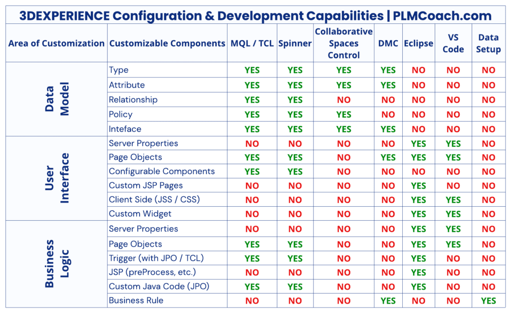
Please note the following important points regarding the tools associated with customization of 3DEXPERIENCE platform:
- Spinner is an automated tool that is used to work with Administrative Objects and certain Business Objects, like Trigger and Auto Number Generator objects.
- Spinner tool is not part of the OOTB package. For terms and conditions regarding purchasing Spinner license, please get in touch with your DS contact.
- Eclipse and Visual Studio Code are standard code IDEs. Developer may use other IDEs of their choice
- Data Model Customization app has a tool named Business Rule Editor for working with Business Rules
Get Trained on 3DEXPERIENCE from PLM Coach
Software Development and Customization Lifecycle
- During this phase, the development team collects input from stakeholders involved to identify overall requirements of the client.
- The tangible deliverables produced from this phase is a requirements document which guides developers throughout the development process.
- After the initial define stages are complete, developers will move on to setting up a development environment for working on the solution.
- In this phase, developers will work on building a solution.
- Developers will work on Data Model Configurations, UI Customization, Business Logic Customization, etc.
- In this phase testers will evaluate the developed solution.
- The solution developed must go through a series of tests, to ensure all the developed functionality is inline with the Requirements document.
- Any bugs found in the code during testing, will be fixed by developers.
- This phase involves the development team packaging, managing and deploying releases.
Get Trained on 3DEXPERIENCE from PLM Coach
Documenting a Customization
The following elements of a customization must be documented:
- Data Model
- Gap with OOTB
- Custom Data Model
- UI Changes
- Evolution made to tables, forms…
- Custom pages
- Custom Widgets
- Business Logic
- Specific Behaviour (Custom Triggers…)
- Custom Lifecycles
- Rules
- Interfaces
- Contract between the interfacing components
- Description of flows
- PnO
- Create Collaborative Spaces, Organizations, Persons, Security Context, Role, etc.
Unified Modeling Language
- Unified Modeling Language (UML) is a standard language for specifying, visualizing, constructing, and documenting the artifacts of software systems.
- The main aim of UML is to define a standard way to visualize the way a system has been designed.
- We use UML diagrams to portray the behavior and structure of a system.
- Using the UML helps project teams communicate, explore potential designs, and validate the architectural design of the software.
- UML makes the use of elements and forms associations between them to form diagrams.
- Diagrams in UML can be broadly classified as:
Diagrams in UML can be broadly classified as:
Customization Description using UML
- The idea is to describe which diagrams are useful for Customization description and what we can do to organize the model.
- The diagrams that we can use are:
Table comparing Diagram and Purpose
| Diagram | Purpose |
|---|---|
| Deployment Diagram | To describe the different runtime components of the customization and their dependencies |
| Class Diagram | To describe the data model or data model mapping |
| Object Diagram | To have an instanced view of a structure model for instance Even it is not always the best way to represent a known structure concept such as an Engineering BOM |
| Sequence Diagram | To describe the sequence of complex data flows (useful for interfaces with web services for instance) |
| State Diagram | To describe life cycles |
| Use Case Diagram | To capture requirements (Out of Scope of this course) |
Advantages of using UML Diagrams
- Lower development costs
- Before starting the development, you know exactly what you are getting.
- Before starting the development, the right decisions can be made.
- More memory and processor efficient systems can be developed
- Lower System maintenance costs.
- Less overall costs
- Your software will behave as you expect it to. Fewer surprises.
- Less relearning takes place.
- Working with a new developer will be easier.
- Communication with programmers and outside contractors will be more efficient
Get Trained on 3DEXPERIENCE from PLM Coach
Customization Approaches
There are four levels of customization
- OOTB
- The functionality is available as-is, or via a simple configuration
- Parameterization
- A configuration of an existing functionality is needed (e.g. new form field or table column).
- No specific code change is required.
- Adaptation
- Some code development is required for producing the desired behavior on an existing functionality
- Complex validation of attribute values.
- Development
- The functionality does not exist and has to be developed from scratch.
- While setting up the 3DEXPERIENCE platform for use, configuring the platform in the Baseline mode (OOTB) should be the first choice for the customer. This would ensure that there are no upgradability issues in the future.
- Customization of application should be attempted only as a last resort, when no Baseline solution matches the business requirements.
Get Trained on 3DEXPERIENCE from PLM Coach
Customization Process
There are several ways to build a Customization corresponding to the Customer Requirements.
- “Top -Down” approach
- User-Interface Driven
- “Bottom-up” approach
- Data-Model Driven
- “Hybrid” approach
- Presents both systematically
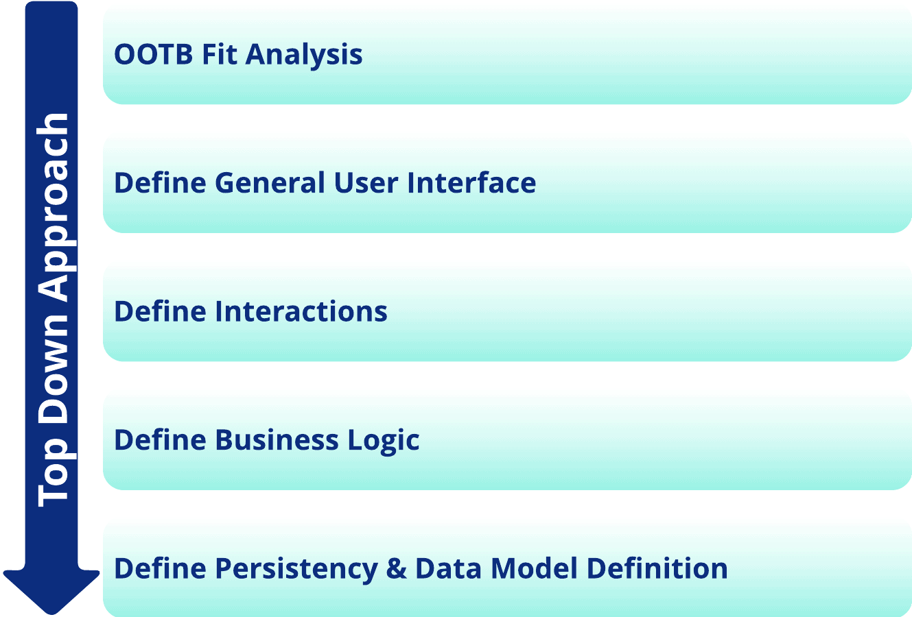
Customization Process – Top Down
In the Top Down approach, work is made with the functional team / customer in order to define UI (table and forms) for all functional entities.
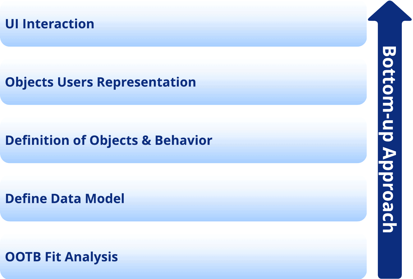
Customization Process – Bottom Up
In a Bottom-Up approach, we usually start with the Data Model Definition for each entity, and infer all the User Interface Elements from it.
Get Trained on 3DEXPERIENCE from PLM Coach
Customization Process – Hybrid
- In the Hybrid approach, entities are both described from the User Interface point of view and from the Data Model point of view.
- This approach is usually the more exhaustive and the more complete from a specification
- This is more time-consuming, and more resistant to changes (less agile)
Get Trained on 3DEXPERIENCE from PLM Coach
Building a Development Environment
Eclipse
- Eclipse is an Integrated Development Environment (IDE) is a software for building applications that combines common developer tools into a single graphical user interface (GUI).
- Install and Configure Eclipse
SonarQube
- SonarQube is a free and open source “code quality platform”.
- SonarQube is an automatic code review tool to detect bugs, vulnerabilities and code smells in your code.
- It runs the rule validations on the server and analyzes all the source lines of your project on a regular basis.
- It can integrate with your existing workflow to enable continuous code inspection across your project branches and pull requests.
SonarLint
- SonarLint is an IDE extension that helps you detect and fix quality issues as you write code.
- SonarLint extends Code Quality and Code Security to your IDE and helps you write clean, safe code.
- Like a spell checker, SonarLint squiggles flaws so that they can be fixed before committing code.
Programming Mistake Detector (PMD)
- PMD is an open source static source code analyzer that reports on issues found within application code.
- PMD includes built-in rule sets and supports the ability to write custom rules.
- PMD does not report compilation errors, as it only can process well-formed source files.
- It can be used to automatically scan
- Possible bugs – empty try/catch/finally/switch statements
- Dead code – unused local variables, parameters and private methods
- Suboptimal code – wasteful String/StringBuffer usage
- Overcomplicated expressions – unnecessary if statements, for loops that could be while loops
- Duplicate code – copied/pasted code means copied/pasted bugs
- PMD is a static source code analyzer which finds common programming flaws like unused variables, empty catch blocks, unnecessary object creation, etc. whereas SonarLint is an IDE extension that helps you detect and fix quality issues as you key-in the code.
Get Trained on 3DEXPERIENCE from PLM Coach
Developing a Solution
Data Model
- Data Model defines how objects are related to each other and how they interact with each other.
- A Data Model illustrates object types used by an application and the relationships that connect them.
- Each Data Type can have any number of attributes defined for it.
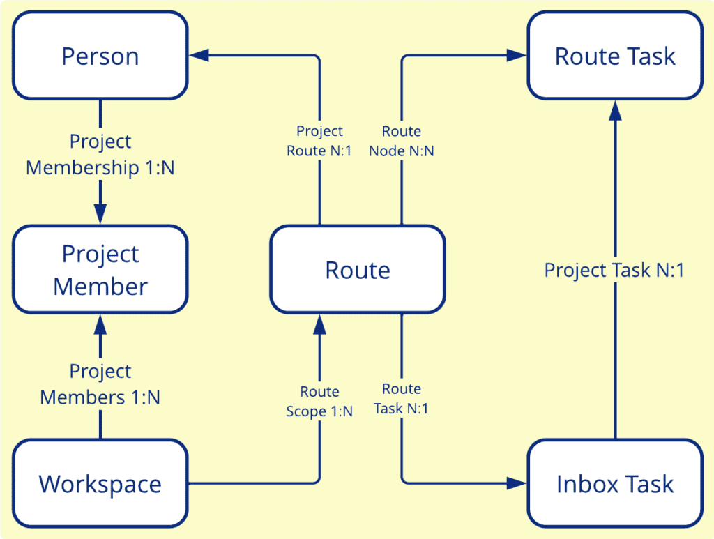
- The graphic is an example which shows the data model for Route.
- Each rectangular box represents a type of business object.
- In this example,
- Person and Project Member are Types whose instances are connected with Project Membership Relationship.
- Person Type is on from side and Project Member Type on to side.
- For Project Membership relationship cardinality is One-to-Many
Get Trained on 3DEXPERIENCE from PLM Coach
Instance Reference Port Connection (IRPC) Data Model
- The IRPC Data Model is the core model of 3DEXPERIENCE platform Native Apps (CATIA, etc.)
- VPM Modelers are defined in the dictionary based on a Type/Relationship pattern
- The PLM Core Modeler is the base of all the VPM Modelers, and is defined by the following:
- 6 Types
- PLMCoreReference
- PLMCoreInstance
- PLMCoreRepReference
- PLMCoreRepInstance
- PLMPort
- PLMConnection
- 3 Relations
- Aggregation
- Is Instance Of
- Points to
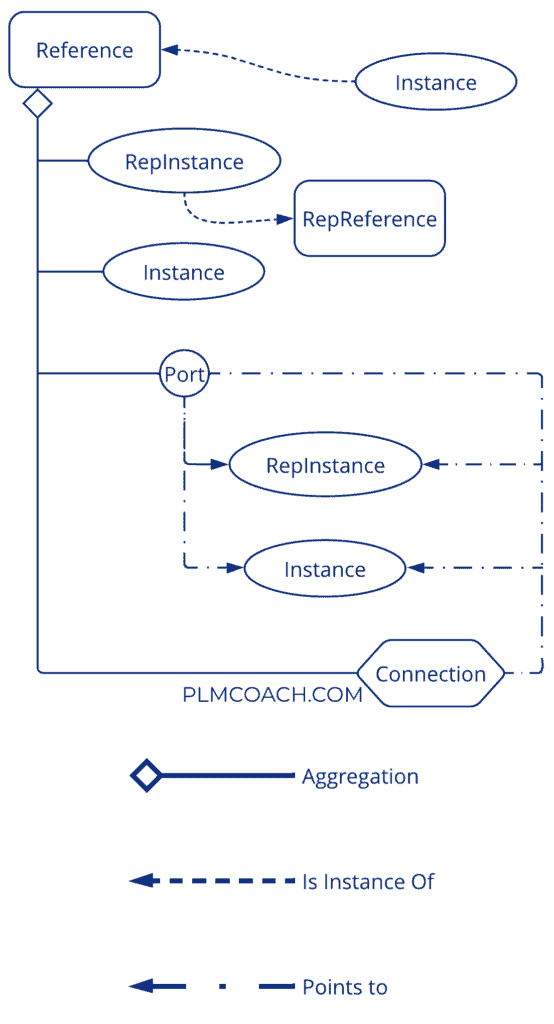
PLM Core Modeler
- The 6 basic classes called PLM Core Class have their own PLM attributes and their own behaviors:
- PLMCoreReference
- PLM building block
- Cannot be aggregated
- PLMCoreInstance
- Instance of a Reference
- Aggregated by a Reference
- PLMCoreRepReference
- Points on Geometry
- Cannot be aggregated
- PLMCoreRepInstance
- Instance of a RepReference
- Aggregated by a Reference
- PLMPort
- “Exposes” an Instance or another Port
- Aggregated by a Reference
- PLMConnection
- “Connects” Instances or Ports
- Aggregated by a Reference
- PLMCoreReference
Get Trained on 3DEXPERIENCE from PLM Coach
Entity Relationship (ER) Model
- The Entity Relationship (ER) Data Model is the core model of 3DEXPERIENCE platform Web Apps (3DSpace)
- Entity Relationship (ER) Data Model is a graphical representation of entities and their relationships to each other.
- ER Data Model is also often referred to as an ER diagram
- The ER Data Model relies on the notion of Entities and Relationships that can be defined between two Entities
- It is typically used in computing in regard to the organization of data within databases or information systems.
- An entity is a piece of data-an object or concept about which data is stored.
- The Three main objects in the Data Model are :
- Types, to define the entities and these entities can have Attributes that define its properties.
- Relationships, defined between Types.
- Interfaces (or Extensions), that allow the addition of extra Attributes to Business Objects, under specific circumstances
- The Policy is a mandatory object which defines the behavior of a Type. It defines:
- Revision sequence
- Lifecycle
- Access control
- Signatures
P&O Customization Practices
- In V6R2013x a new access model was introduced that could coexist with the old model
- “People and Organization” (P&O) is the term commonly used to refer to the new access model
- P&O is now called as Organization Modeling & Secure Data Accesses
- It is the main security mechanism to manage authorizations for 3DSpace
- P&O consists of five key concepts at its foundation:
- Roles, People, Organization, Collaborative Spaces and Security Contexts.
Get Trained on 3DEXPERIENCE from PLM Coach
P&O Elements
- Person
- A Person object represents a logical user in the 3DEXPERIENCE platform.
- Person is assigned product licenses (“Named User” licenses).
- The licenses usually appear to the end user as Roles in the compass.
- Collaborative Space
- A Collaborative Space represents a shared space where people can work together on content/data.
- Collaborative Spaces are mainly used for access management.
- Used for making up Security Contexts, and stamping objects’ Ownership vectors
- Organizations
- Organization object’s purpose is to define a group of persons belonging to a same operational entity.
- Roles
- Roles represents the area of work, or access level of a person.
- Depending on the operation mode of the application, two separate categories of roles are available .
- Baseline Roles
- Customer Specific Environment (CSE) Roles
- Security Context
- A Security Context is defined by the combination of one Organization, one Role and one Collaborative Space.
- A Person is always related to at least one (or multiple) security context(s)
- The Active Security Context is used to set the initial data ownership, when a user creates data.
Get Trained on 3DEXPERIENCE from PLM Coach
3DSpace User Interface (UI) Customization

- The User Interface consists of the following:
- Application Login
- Navigator Page / Toolbars – Top Bar, Navigation pane, Page Toolbars
- Global/Generic/Type ahead and 3DSpace Index (Full Text Search) components
- Application Specific Search Pages and Filters
- Forms in create/edit/view modes.
- Flat and Structure Browser Tables
- Categories menu / Structure Navigator Pages
- Configurable Web Forms, Configurable Type and Vault Chooser Forms
- Calendar Popup Forms
- Configurable Charts
- Grid Tables
- Configurable Structure Compare Reports and Advanced Structure Compare
- PowerView Configurable Pages (Portal Pages)
- The customization of these components are done through MQL, TCL or Spinner.
IFWE Compass
- The Compass provides access to your roles, apps, and services.
- The Compass is the door to all 3DEXPERIENCE platform services, apps and portfolios.
- It allows 3DEXPERIENCE users to access their available roles and apps, and discover the entire Dassault Systèmes solutions portfolio.
App-Based UI Architecture
- Invoking emxNavigator.jsp is now contextual and depends on an APP.
- Former “My Desk” menu content depends on the APP.
- We can access the Home Page of an APP with the appName URL Parameter
- When calling emxNavigator.jsp, pass these URL parameters and appropriate values:
- MenuName – Defines which application submenu should be expanded when the Navigator page is called.
- CommandName – Defines the name of a command object to define the page that should be displayed in the Content frame
- ContentPage – Defines the JSP that should appear in the Content frame
- objectId – Defines the business object whose navigation tree should be displayed when the Navigator window is called.
3DSpace Schema Agent (Spinner)
- 3DSpace Schema Agent (Spinner) eases the burden of migrating schema from a source to target environment, eliminates the need for scripts and enables offline review and modification of schema.
- This tool is widely-used by customers for 3DSpace implementations and upgrades as it helps manage or modify schema and is convenient to use.
- Spinner is a platform independent dynamic scripter that streamlines the process of adding, updating and pushing schema changes into the 3DSpace database while reducing manual and scripting errors during an implementation, upgrade or migration.
- Spinner is designed to utilize tab-delimited text files through the command line feature of the PLM Modelling Studio (MQL).
- It is not an import/export procedure, rather a script consisting of MQL – add and modify commands to push schema changes
- Spinner saves up to 60% of the time normally required to upgrade and manage their 3DSpace environments
- No need for prior programming experience or detailed knowledge of MQL, to use
- Significantly reduces manual and scripting errors during implementation, upgrade or migration.
- Spinner can now be used to export and import Widgets, custom Data Model Customization Packages
- Spinner is compatible with PnO elements like Company, Person and Security Contexts.
Key Highlights of Spinner Utility
- Require no prior programming experience.
- Enables offline review and modification of schema
- Reduce manual and scripting errors during an 3DSpace implementation, upgrade or migration.
- Easier and faster to add, update, and migrate schema changes
- Platform independent (Database, OS, etc.)
- No changes or additions necessary via Business Modeler.
- The Spinner tool is not available in OOTB. Please get in touch with concerned Sales team to obtain installer and license for Spinner utility.
JPO Programming Rules
- In order to segregate standard AEF JPO source code from application specific source code, inheritance mechanism has to be used.
- Base classes provide standard application behaviours (emxNameBase). They should not be modified or customized under any circumstances.
- Classes derived from Base class should not contained application specific behaviours.
- Classes that are derived from Base serve as the entry points for the application specific behaviours (ApplicationName).
- All references have to be done through a derived class.
- All customizations to a JPO are to be placed in the Derived class, as mentioned below:
- New customized methods are to be placed in Derived class only
- If there is an absolute necessity to customize a function from the Base class, then the concerned methods should be first overridden in the Derived class. The overriding method should contain the customized code.

Testing and Debugging
- Software Testing is a process, to evaluate the functionality of a software application with an intent to find whether the developed software met the specified requirements or not and to identify the defects to ensure that the product is defect free in order to produce the quality product.
- It is a process of identifying the correctness of software by considering all its functionalities and attributes (Reliability, Scalability, Portability, Re-usability, Usability) and evaluating the execution of software components to find the software bugs or errors or defects.
- Software Testing methodology can be categorized into the below categories:
- Black-Box Testing
- Black-Box Testing is a software testing method in which the functionalities of software applications are tested without having knowledge of internal workings of the application.
- Black-Box Testing involves testing from an external or end-user type perspective.
- White-Box Testing
- White-Box Testing is the detailed investigation of internal logic and structure of the code.
- In White-Box Testing an internal perspective of the system, as well as programming skills, are used to design test cases
- Grey-Box Testing
- Grey-Box Testing is a technique to test the application with having a limited knowledge of the internal workings of an application.
- It is a combination of Black-Box and White-Box testing.
- Black-Box Testing
Get Trained on 3DEXPERIENCE from PLM Coach
Types of Software Testing
- Functional Test: It is a type of Black-Box Testing that bases its test cases on the specifications of the software component under test. It is performed by testing teams.
- Integration Test (~ UI Testing in a web application context): The purpose of an Integration Test is to replay a whole scenario.
- Monkey Test: The idea of a Monkey Test is to test “edge” cases by performing random actions in the application.
- Performance Test (also Capacity and Scalability): The idea is to observe how the application behaves when used by a large amount of concurrent users, or with a huge data set.
- Smoke Test: The idea of a Smoke Test is to have a simple way of saying that the application seems to be working (e.g. we can login and create an object or make a search)
- Unit Test: The basic test of a code. A Unit Test should be repeatable and isolated. The idea is often that when testing a method with good input we get expected results and when testing with wrong inputs we get an exception.
Unit Testing and Test Driven Design
- Unit Testing is a type of software testing where individual units or components of a software are tested.
- Test Driven Design (TDD) is software development approach in which test cases are developed to specify and validate what the code will do.
- In TDD test cases for each functionality are created and tested first and if the test fails then a new code is written in order to pass the test, while making the code simple and bug-free.
- The classic usage of Unit Testing for TDD is in the RED-GREEN-REFACTOR cycle, as shown below:

Get Trained on 3DEXPERIENCE from PLM Coach
Build and Release
Version Control System
- Version Control is the practice of tracking and managing changes to software code.
- Version control systems are software tools that help software teams manage changes to source code over time.
- Git is a free and open source distributed Version Control System designed to handle everything from small to very large projects with speed and efficiency.
- Distributed (allows offline work and prevents from single points of failure)
- Powerful Branch Management System
- As an alternative, it is possible to use SVN. SVN (Subversion) is an open source centralized Version Control System used for maintaining current and historical versions of projects.
- With a centralized system, all files and historical data are stored on a central server.
- In many cases, the VCS can be paired with a Web Application in order to manage access in a easy way
- Gitlab for Git
- uSVN, WebSVN for SVN.
Build and Release Management
- Build and Release Management is the process of managing, planning, scheduling, and controlling a software build throughout its lifecycle.
- Build and Release management will
- control the life cycle of a software product
- the process of planning, managing, scheduling, and controlling the build in different stages and environments, like development, testing, staging, and production stages.
- Different build tools can be use to compile the source code files into reusable executable files or packages and automate the process of build deployment.
- We can make use of a build & release management tool called Maven, in addition with an Artifact Repository called Nexus.
- Maven is a declarative project management tool that decreases the overall time to market by effectively leveraging cross-project intelligence. It simultaneously reduces the duplication effort and leads to higher code quality.
- Nexus adds a way to store third-party dependencies, deliverables and offer a simple portal in order to retrieve them (useful for qualification and operation teams).
- Alternatives can be Ant scripts (paired with Ivy for Dependency Management), or Gradle.
Software Configuration Management (SCM)
- What is Software Configuration Management?
- Software Configuration Management (SCM) is the task of tracking and controlling changes in the software.
- Why use Software Configuration Management?
- Defines where the source code will be stored throughout the project.
- Ensure all changes to the source code are archived in an history log for later reference.
- Secure source code with regular backups for later recovery.
- One source for all projects.
Get Trained on 3DEXPERIENCE from PLM Coach
Continuous Integration System
- Continuous integration (CI) is the practice of automating the integration of code changes from multiple contributors into a single project.
- Jenkins is one of the best options for a Continuous Integration system. Jenkins is the de-facto standard in software development.
- It provides a clean and intuitive interface, simple build configuration, and a lot of plug-ins and connectors with several tools.
- Alternative to Jenkins is GitLab CI/CD tool. GitLab CI/CD is a tool built into GitLab for software development through the continuous methodologies:
- Continuous Integration (CI)
- Continuous Integration works by pushing small code chunks to your application’s codebase hosted in a Git repository
- Continuous Delivery (CD) or Continuous Deployment (CD)
- Continuous Delivery and Deployment consist of deploying your application to production at every push to the default branch of the repository
- Continuous Integration (CI)
- With GitLab CI/CD, you can test, build, and publish your software with no third-party application or integration needed.
3DEXPERIENCE Customization – FAQs
The 3DEXPERIENCE Platform is a powerful and versatile solution that empowers companies to transform their business processes and enhance their product development lifecycle from ideation to delivery.
ENOVIA is a specialized PLM solution focused on managing product data and collaboration, the 3DEXPERIENCE Platform is a broader business platform that integrates various applications, including ENOVIA, to enable end-to-end product development, collaboration, and digital transformation.
Configuration is about adjusting settings within the given options, while customization involves modifying the software’s code or functionality to introduce new features or tailor it more extensively to specific needs.
3DEXPERIENCE native apps are platform-specific software applications for mechanical design and simulation installed on Windows client machines, while 3DEXPERIENCE web apps are accessed through web browsers on Windows clients. Native apps offer optimized performance but require installation and updates, while web apps provide platform independence and easy access without the need for local installation.
Platform Management
Collaborative Space Control & Configuration
Data Model Customization
Data Setup
Checkout our other articles on 3DEXPERIENCE


Nice Post! Thanks for sharing with us.